![]()
![]()
![]()
![]()
The detector for all these measurements can be a photometric sensor, a tristimulus instrument, a spectroradiometer or a Video photometer. The application of spectral resolving technique allows to get more information about the DUT and reduces the measuring uncertainty because the Color Matching functions are applied directly. Therefore this technique becomes more and more important and is now the prefered one for LEDand SSL measurements.
The currently relevant publications for the measurements are CIE 127:2007 for Low Power LEDs and IES LM-79 and CIE S 025/E:2015 for High Power LEDs and SSL products.
Goniometer and nearfield goniometer are used to measure the angular distribution of LEDs (Light distribution curve – angular distribution of Luminous intensity). This measurement is time consuming, but delivers the most extensive data set of a light source. The integral values like Luminous and Radiant flux will be calculated as summation of the light distribution data. “Color quantities shall be measured as values that are spacially averaged over the entire solid angle …” (from: IES LM-79).
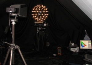
Goniometer with specbos 1211-2 © olino.org
Commonly photometric or tristimulus detectors are used for such measurements. If the distribution of the spectral characteristics is of interest in addition, a spectroradiometer as specbos 2501 can be applied as detector of the goniometer. Due to its high sensitivity the measuring time for each step becomes acceptably short. The instrument can be equipped with a remote diffusor (Diffusor with fiber optic extension) so that the installation will be very flexible.
The integral values like Luminous and Radiant flux will be calculated as summation of the light distribution data.
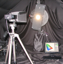
Goniometer with specbos 1211-2
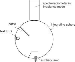
If a goniometric scan is too slow and only integral values are of interest (e.g. in production), the measurements can be done with an Integrating sphere. This sphere contains at least two ports – one for the sample and one for the probe. A baffle is needed to avoid direct incidence of the sample light to the probe. The probe is calibrated for Radiant flux, but basically measures the Illuminance in the plane of the inner sphere surface. The sphere needs to fulfil the following requirements to guarantee an almost equal illuminance on all surface parts (that the illuminance at the measuring location is representative for the whole sphere wall):
The CIE publication 127:2007 / IES LM-79 and CIE S 025 define the conditions for such Luminous Flux measurements.
There exist three different sphere measuring set ups according to these publications:
Measurement geometry for LEDs with no backward emission (2π geometry)
specbos 2501/500 is the combination of specbos 2501 device with a hinged 500 mm sphere with an auxiliary lamp. It can be used for 2 π and 4π measurements. The correction of self absorption is especially necessary for the 4π geometry where the full sample is inserted into the sphere and thus may drastically disturb the conditions in the sphere.
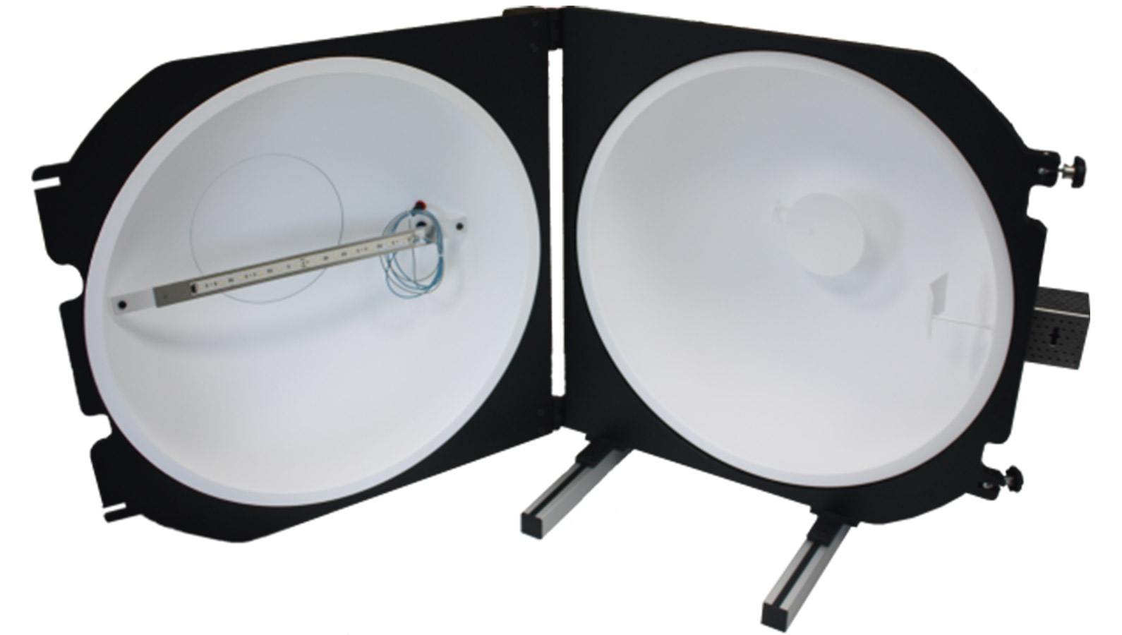
specbos 1311 (500 mm hinged sphere with auxiliary lamp)
The detector for the measurements can be a photometric detector, a tristimulus instrument, a spectroradiometer or a videophotometer.
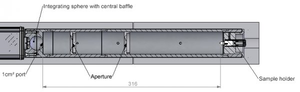
The Luminous Intensity (cd) measurement is normally carried out as an Illuminance measurement. It can be done with the set up described in the CIE publication 127:2007. The main idea of this set up is that the adjustment of the sample is done according to mechanical conditions – the measuring distance is measured from the tip of the LED and the angular adjustment is done with regard to its mechanical axis.
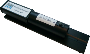
Condition A
The measuring result is called Averaged LED Intensity rather than Luminous intensity because it is not necessarily the maximum value of the LED.
The specbos 2501 in combines with the measuring tubes and the measuring integrating sphere according to CIE 127:2007 allows the photometric measurement of the LEDs. Two measuring distances (cond. A – 316 mm and cond. B – 100 mm) can be used.
specbos 1401 condition B
If a CIE 127 measuring set up for Luminous Intensity is not available, the measurement can be done with a Luxmeter on an optical bench (see: Radiant Intensity Calculation using Irradiance Measurement).
specbos 2501 integrating sphere or tube CIE127 type A and B