![]()
![]()
![]()
![]()
The following measuring set ups can be used to characterize energy saving lamps and conventional fluorescent tubes:
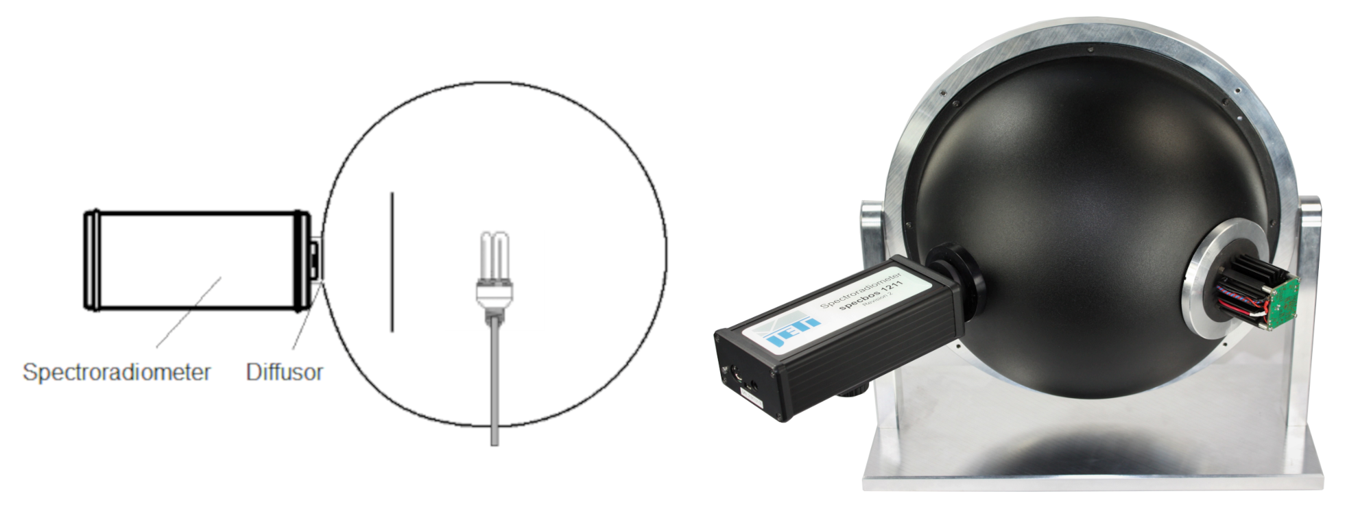 Characterization of a fluorescent lamp by its luminous flux |
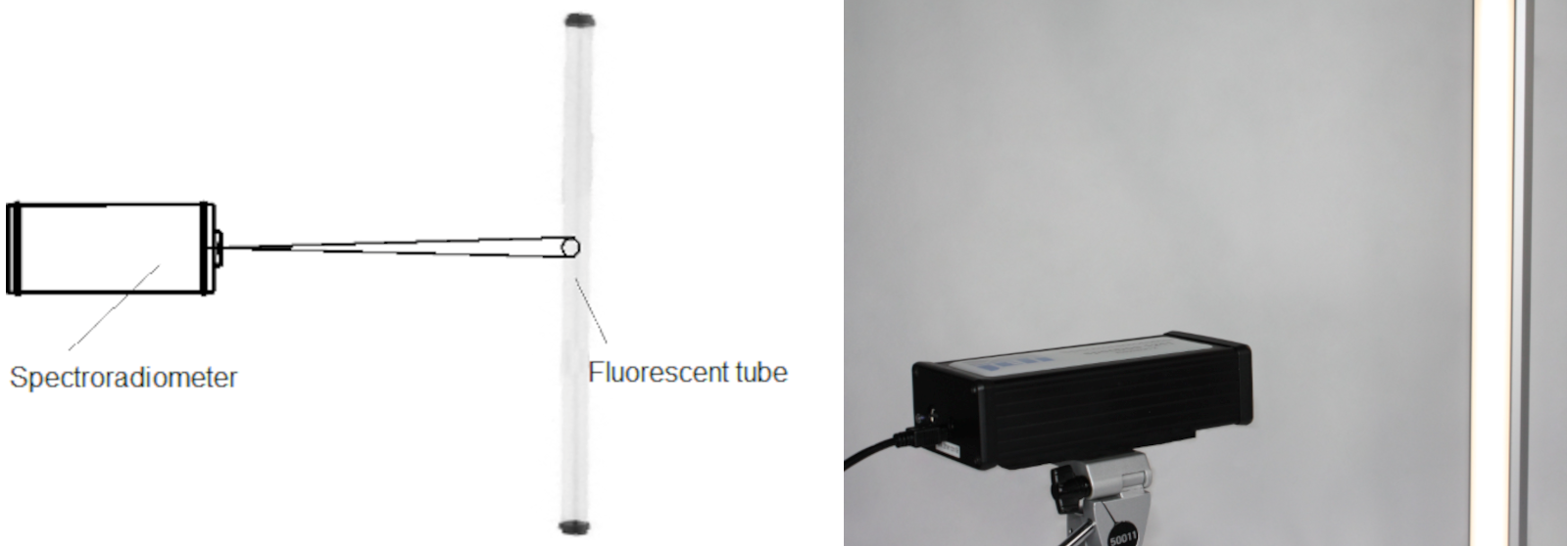 Characterization of a conventional fluorescent tubes by its luminance |
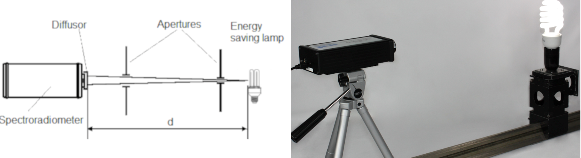 Characterization of a energy saving lamp by its luminous intensity |
The common measuring set ups to characterize the photometric and colorimetric properties of fluorescent lamps are Goniophotometers and Integrating sphere systems. The latter are especially used in production because of their much higher measuring speed (left figures). The diameter of the sphere needs to fit to the tube dimensions, therefore spheres with 1 ... 3 m diameter are necessary for long fluorescent tubes.
Point like sources as compact energy saving lamps can also be characterized by their Luminous intensity (figures in centre). The measurement is based on a illuminance measurement and afterwards converted into the luminous intensity value (see: Radiant Intensity Calculation Using Irradiance Measurement). Here the the measuring distance has to be large enough.
Fluorescence tubes can be characterized in Luminance mode (see right figures). It allows to get the result from a selected part of the tube surface. Repeated measurements on different locations allow to obtain a distribution along the tube. The measuring diameter can be adapted by changing the measuring distance of specbos 2501 to the tube. The target circle of specbos 2501 can easily be used to adjust the measuring position on the tube
Each luminescence material has its characteristic spectrum. Different materials will be mixed according to special receptures to achieve desired chromaticities and color temperatures of fluorescent lamps. It is necessary for quality control to monitor these data and the prefered method is to measure the spectra by a spectroradiometer and calculate the values.
McAdam ellipses are used to specify the chromaticity tolerances. These ellipses were defined by McAdam in 1943 and are still used in lamp industry [1]. They show the areas in the xy or uv diagram wherein the human eye cannot distiguish between different colors. They are different in size and orientation across the color gamut.
Some ellipses covering the black body locus are used to specify fluorescent lamps. They are defined for several color temperatures from 2700 to 6500 K for industrial use (see the standards for US [2] and for EU [3]). It is defined the central location of xy and the accepted tolerance ellipses. The used equiation for the ellipses is as follows:
![]()
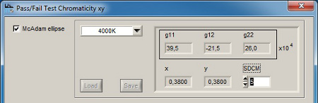
g11, g12 and g22 are the individual coefficients for each ellipse, Δx and Δy are the deviations from the rated values x and y and SDCM means standard deviation of color matching (tolerance factor or McAdam Color steps). So the ellipses are defined in position, orientation and size.
SDCM is a scaling factor and can be varied between 1 and 10 to vary the ellipses for different tolerance requirements. The value of 1 for SDCM characterizes the original ellipse of non distinuishable chromaticities. Higher values are used to extend the tolerance ranges with regard to the costs and yield of the production. The software JETI LiVal contains these definitions of ellipses, therefore it can be easily used for the characterization of fluorescence lamps in production process.
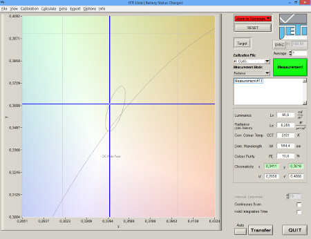
Detail of xy diagram with a defined ellipse
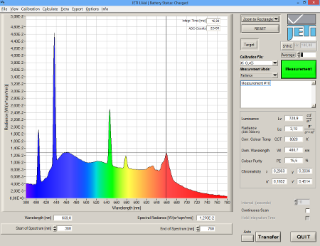 Spectrum of a fluorescent lamp, measured with specbos
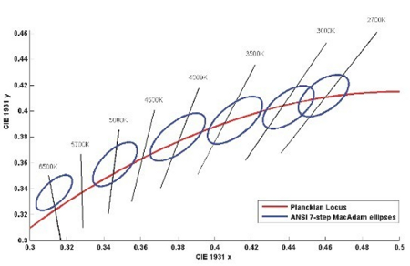
McAdam ellipses for different color temperatures in the region of the Planckian radiator in the xy diagram
Detail of xy diagram with a defined ellipse
| Color type | Color temperature | Name | x | y | g11 | g12 | g22 |
| F 6500 |
|
|
|
|
|
|
|
| F 4000 |
|
|
|
|
|
|
|
| F 3500 |
|
|
|
|
|
|
|
| F 3000 |
|
|
|
|
|
|
|
| Color type: F 6500 |
Color temperature:
|
Name:
|
x:
|
y:
|
g11 :
|
g12 :
|
g22 :
|
| Color type: F 4000 |
Color temperature:
|
Name:
|
x:
|
y:
|
g11 :
|
g12 :
|
g22 :
|
| Color type: F 3500 |
Color temperature:
|
Name:
|
x:
|
y:
|
g11 :
|
g12 :
|
g22 :
|
| Color type: F 3000 |
Color temperature:
|
Name:
|
x:
|
y:
|
g11 :
|
g12 :
|
g22 :
|
[1] Specification of Small Chromaticity Differences. MacAdam, D.L.: JOSA 33(1943) 1, p. 18-25
[2] ANSI C78.376-2001
[3] EN 60081:1998, appendix D
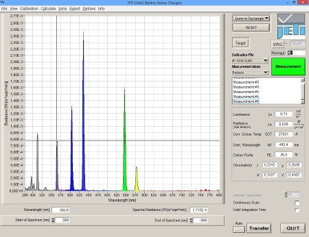 UV exciting tube and its spectrum